Cosmic Ray Telescope Software
- SOFTWARE DEVELOPMENT IS STILL GOING ON; SOME CONTROLS COULD BE DEACTIVATED
- SOFTWARE HAS BEEN DEVELOPED FOR THE RPi 4; IT COULD BE SLOW ON PREVIOUS MODELS
- ADC/DAC FOR SETTING/SENSING ARE NOT CALIBRATED; THERE MAY BE A DIFFERENCE BETWEEN SENSING/SETTING VALUES DUE TO COMPONENTS TOLERANCES
>>> click here to download PDF version <<<
Quick Start
SiPM Panel
- Click tools and select UnlockVmax
- Set Vmax value according to the SiPM type (56V or 67V)
- Turn On Main HV generator
- Set the SiPM operating point according to the SiPM type (55.7 0r 66.6). Note: sense value can be different from the set value as ADC/DAC must be calibrated
- Set a 30/40 mV threshold value
Trigger Panel
- select (at least) 2 instrumented layers;
- Push the set trigger button (the trigger conditions will be written);
- Leave the time format default selection (sec):
- Leave Timer default conditions (Single)
- Enter the countdown timer value (default: 100 sec)
- Start the measurement
Advanced Panel
- Turn Main HV off
- Select the SiPM using radio button
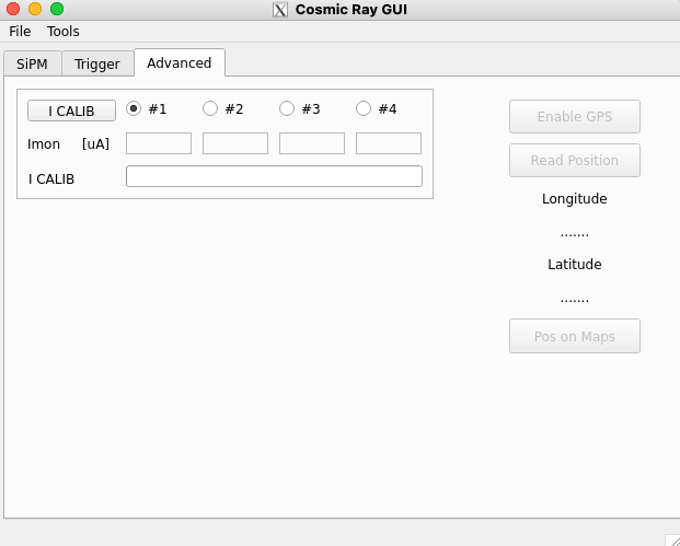
- Click ICalib; at the end of the procedure the offset value will be written in the dedicated field and yellow background will be set to indicate the offset measurement has been completed
Contents
1 – SiPM Panel
2 – Trigger Panel
3 – Advanced Panel
4 – Usage Example
1 – The SiPM Panel
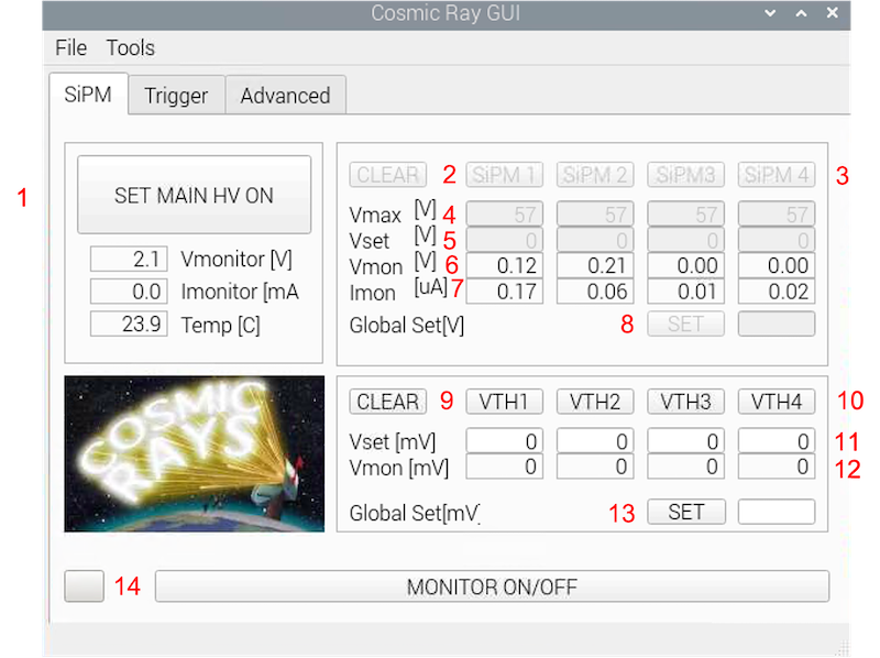
- turn on/off the main generator
- clear SiPM supply voltage
- set voltage on the selected SiPM (or press return after entered the value)
- maximum voltage for SiPM (to change the values: Tools – Unlock Vmax)
- SiPM voltages
- SiPM voltages monitor
- SiPM current monitor
- set SiPM voltage for all SiPM
- clear comparator thresholds
- set threshold on the selected SiPM signal (or press return after entered the value)
- threshold value for the selected SiPM signal
- threshold monitor
- set signal threshold value for all SiPM
- sensing on/off
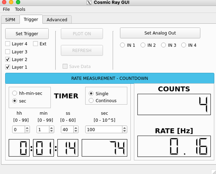
The Trigger panel allows to select the layers that will contribute to trigger generation. For example assuming Layer 1 and Layer 2 are selected, as shown in Figure 3, the trigger will be generated and the counter incremented only if both signals are present within a 100 ns time window. To start a measurement click the RATE MEASUREMENT – COUNTDOWN button
2 – The Trigger Panel
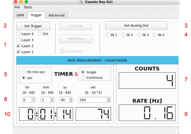
- layers selection
- set trigger conditions
- output the analog monitor signal
- select the monitor input
- select the countdown time format
- select single or continuous measurement (default: single)
- the counter (cleared when countdown is started)
- set the countdown time according to the time format (hh:min:sec or sec)
- rate measurement
- countdown timer
Finally the Advanced Tab (at the moment) allows to calibrate the SiPM current measurement.
3 – The Advanced Panel
4 – Usage Example
As an example let we assume there is a tile connected to SiPM1 channel. To set the SiPM operating voltage use the following procedure:
- Set the maximum operation voltage to prevent SiPM damaging:
- using the Tools menu voice enable the Vmax setting
- enter the maximum operating voltage for the selected SiPMs (operating voltages are shown on the tile cover; set a value equal to Vop + 2 V )
- disable the Vmax setting.
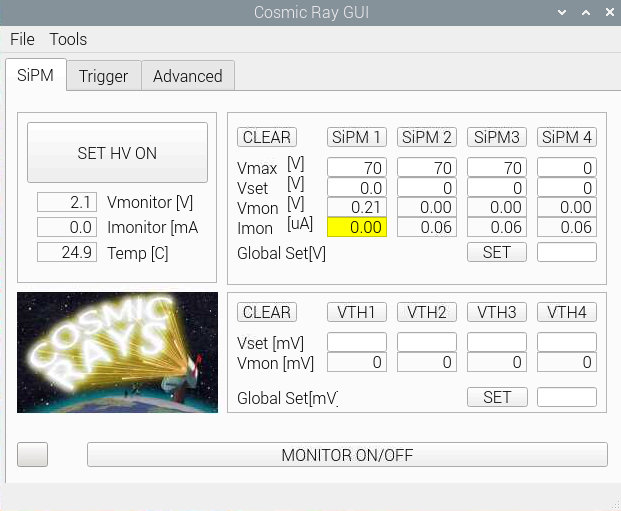
- Enable the Main Generator; the GUI will change as shown below allowing the setting of SiPM supply voltages; a control will be executed on the setting voltage: if the voltage is not in the allowed range (0 to Vmax) or is not a numeric the field will be cleared.
Please note: both Current Monitor (Imon) and Voltage monitor (Vmon) should be calibrated to account for component tolerances and/or device offset (see dedicated section for current calibration). When the sensing parameter has been calibrated the label background color is set to yellow.
| MAIN HV enabled | Imon 1 SiPM calibrated |
|---|---|
 |
 |
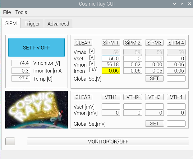
Below an example of setting parameters for a S13360-1350Cs HAMAMATSU MPPC and a screenshot of the preamplifier output; the fast and the slow component of the SiPM signal are clearly visible (high BW scope is required to distinguish the two components).
| SiMP1 Voltage Set | Oscilloscope SiPM Preamplifier Signal |
|---|---|
 |
 |
Set the same working voltage for SiPM2 and select the Trigger Tab. Check Layer 1 and Layer 2 (assuming you have connected the two tiles to SiPM1 and SiPM2 inputs) and click Set Trigger button. A trigger will be generated a counted only if both signals are in coincidence within a 100 ns time window.
